Tuesday, September 29, 2015

Custom Stairway + Hallway Lighting Project - Part 3

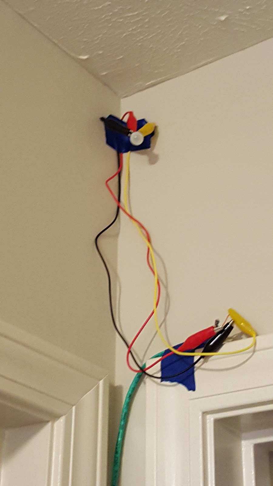
At the end of my last writing the last thing I needed to do before ordering stuff was to test my PIR sensor in the hallway to get a feeling of if it would provide sufficient detection.  Using some painters tape, old cat5e, and some leads, I taped up a sensor roughly where it will go.  It looked terrible, but it got me what I needed.  A single sensor reliably covered about 1/2 to 2/3 of the hallway.  2 sensors would work as planned.  

I did some additional software work to support the muxing and to also take a slightly different approach to the averaging code for the active IR sensors.  (Thanks to my Father-In-Law for the idea).  Originally I had it set up to store each sensor reading for a given IR sensor in an array (within the class instance) and then on each read, move a pointer to a element of the array and update it with the new reading.  Then I would iterate through the array, sum, and average the results.  My father-in-law suggested that I keep the array, but instead do something a little different that would require no iteration.  Basically I would hold a internal variable that is the current sum of the last 4 readings.  When the read starts I would add the value of the read, move the array pointer forward one (which would then cause the pointer to be pointing at the oldest element in the array), then subtract the value of that element in the array from the total.  Then I could simply divide the running total by the number of elements (in this case 4).  This eliminated the iteration and worked fantastically. Here is the DistanceSensor class:


class DistanceSensor : public Sensor{

 int PIN;
 int stackLocation;
 double triggerDistance;
 bool debug;
 double total;

 static const int stackSize = 4;

 double avg[stackSize];

 public:
 DistanceSensor(int pinnum, double triggerDist, bool enableDebug) {
  PIN = pinnum;
      triggerDistance = triggerDist;
      stackLocation = 0;
  debug = enableDebug;
  total = 0;

  #ifdef DEBUG
  if (debug) {
   Serial.print("Adding Motion Detector on PIN:");
       Serial.print(pinnum);
       Serial.print(" | Trigger Distance:");
       Serial.println(triggerDist);
        }
        #endif
     
      for (int i = 0; i < stackSize; i++) {
       avg[i] = 100.0;
       total += 100;
      }
 }

 //Keep a running total of the distance as it relates to stack size.  
 //On each read, it will add the newest amount to the total, move the pointer forward one and remove that distance from the total.  
 //This means we don't need to loop through the stack on each read. -  Thanks to my Father-In-Law for this idea.
 bool Get() {
  double distance = 6202.3*pow(analogMuxRead(PIN),-1.056);
  
  avg[stackLocation] = distance;
  total += distance;
  
  //Move us forward one
  if (stackLocation == stackSize -1) {
   stackLocation = 0;
  }else{
   stackLocation ++;
  }
  //Remove the distance from the total for the next.  (basically removing the oldest distance)
  total -= avg[stackLocation];
  
  double temp = total / stackSize;

      #ifdef DEBUG
  if (debug) {
   Serial.print("Distance = ");
   Serial.print(distance);
   Serial.print(" | Average = ");
   Serial.println(temp);
  }
  #endif
  
  return temp <= triggerDistance;
 }
};


 The only piece I have left planned in terms of software is to do some variable lighting levels based on the ambient light.  (So if it is really dark, then the lights won't turn on as bright.  The notion being that you probably are used to the dark and don't need to be blinded.)  This isn't as simple as just finding out the light level and setting the lights output level though as I need to store the value just before the lights turn on.  Otherwise the lights themselves would alter the ambient level and would eventually cause a loop that would ultimately turn the lights on to full brightness.  However the current code doesn't return the light level when I fetch it.  It simply returns whether or not the light level is sufficiently dark to turn on the lights at all.  So refactoring will need to occur here.


I ordered all the parts and eagerly awaited their arrival.  Among them was a screw-down terminal shield from Adafruit (Picture below after I had already soldered all the components).  Also was the 16 channel multiplexer.  I also added screw down terminals to it as well.  My goal here is to solder wires directly to the boards as little as possible.  (In fact I'm hoping to avoid it entirely).

I did have to modify the redboard slightly.  In the lower left you'll see the outline of what used to be the power plug.  It turns out on the redboard with this particular shield that the power plug is just too high (by about 1/8").  Since I'm going to be feeding power via the screwshield to the VIN pin, that plug is un-needed.  So away it went.


I don't have alot of experience with PCB soldering, but overall I think this turned out fairly well.  


Next step was to get the multiplexer working, both in code and wiring.   It looks like a bit of a rats nest, but it works.  I did have a little initial trouble when I forgot to set the pin mode on the digital control pins to output.  This would cause the digital pins to float, which would cause the mux to shift around reading different pins.  Since it was reading different pins most of which weren't hooked up, those would have floating values too.  Needless to say I had some wildly inaccurate results in the logs until I cleared that up.


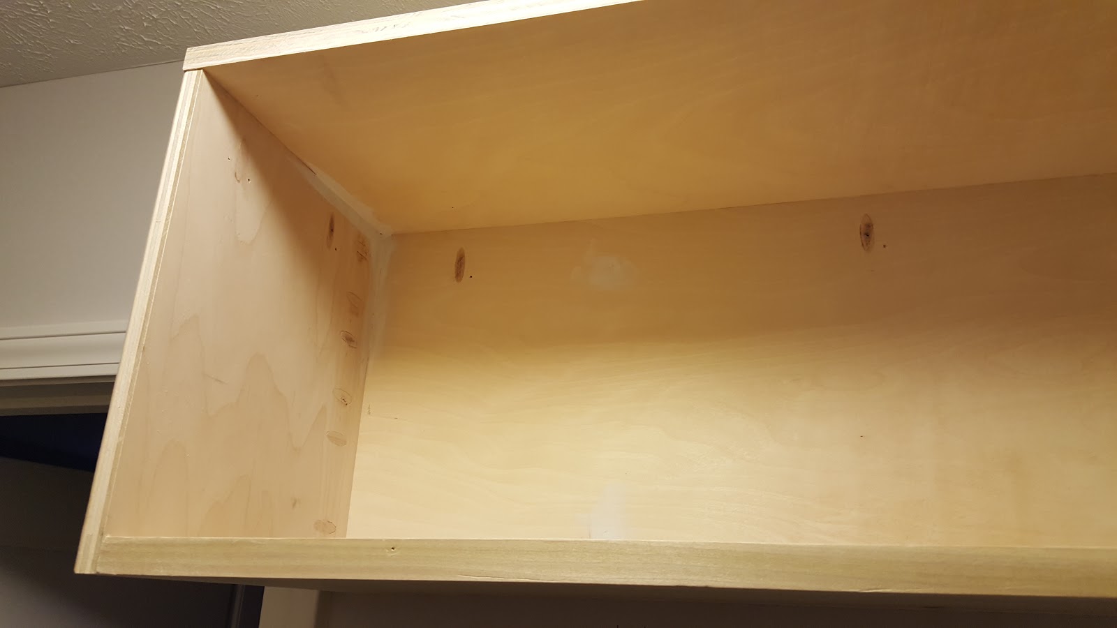
The box I'm putting all this into is roughly 10x6x3 (LxWxH).  The box is going to undergo a fair amount of modifications as well to handle all the input/output.  In the bottom of the box is a set of standoffs.  I cut out a piece of 1/4" poly-carbonate.


I then did a dry fit of the internal components.  I wanted to get a general feel for how everything actually would sit before I started cutting holes in the case.  My plan is to have the left side of the box contain all the sensor inputs. Those will all run into the mux (with the exception of Vcc and Ground which will go straight to the redboard).  On the right side I will have the power input, power switch, power output and USB header (so that I can easily plug in and do diagnostics without having to open the case up).  Somewhere I still need to fit a switch that when closed will cause all lights to turn on to 100%.


I ordered a black 6 port keystone plate for the Cat5e connectors.  It is a little taller than the box when the lid is off, but looks exactly right when the lid is on (which will be 99.9% of the time).  That said, the plate is not black.  Not really.  It's more of a deep brown.  But whatever...


 I have all the ports on the other side put in as well except USB.  I don't know why but I totally spaced on that, so I'll need to put that in tomorrow.  You might notice that just below the power switch there is some plastic that looks terrible.  Yeah....totally cut the hole for the switch a tad too big.  It looks terrible, but I'm not sure how to fix it really. (and I'm not buying a new box).  I do need to erase those pencil lines though.....


Here I have the components in (though still not screwed down) to make sure everything looks good.  It does, so yay!  


So tomorrow I will be getting the screws to screw down the power supply and bus bar.  I already put holes in and screwed down the controller and mux board.  I will also add in the USB header somewhere.  Then I'll start the process of wiring this thing together.  Once that is complete I'll do some basic testing on it and then it will be time to start modifying the handrails for the stairwell.

Mudroom, Part 2 - Finished for Now

I'm waiting for some stuff at work to finish up, so I figured I should get this in while I'm thinking about it.  Over the last few weeks I've gotten the 2nd part of mudroom done.  For this segment I needed to add shelving up near the top and add another set of hooks.  This was, overall, much simpler than the bottom half, though it wasn't without it's frustrations.


The first thing was to put a backboard up on just 1 side.  This is because only 1 side will have 2 shelves.  The other side will have a single shelf.


I, for whatever reason, didn't take a picture in between, but I next added a couple of small pieces for the rest of the top shelf to sit on.  After that I cut the top shelf.  it is all one piece and was a royal pain to get in.  This was, because I've noted before, the walls are not square, but the shelf was.  There was several attempts at getting it into the slot and then having to take it down and trim edges.  Even then I mucked up the drywall in the corners.  Those had to be cleaned up quite a bit.


Next I put in the bottom shelf.  Once again using pocket holes to hold it all together. You might notice that the bottom shelf is a slightly different wood.  That's because I was short by 3 or 4" on the plywood sheet I had to finish this.  And it was 49" wide which meant that I couldn't get another 4'x4' sheet of plywood.  (And I wasn't going to buy a full sheet for 1 piece).  So I ended up getting some poplar.  Once painted it won't look much different.


Next up since this shelf is going to be quite visible I wanted to fill in the pocket holes.  I first put the plugs into the holes with some wood glue and let that set for a day. I also went through and put some putty in a few of the cracks and such to clean up the problems that come from the walls not being square.


Next up I used my oscillating saw to cut down the excess and then used the same oscillating tool's sanding pad to smooth things out.  Seriously, my oscillating tool has to be one of my favorite tools I own.  So versatile.


We needed to move the existing set of hooks, but putting 6 up there felt weird due to their location.  These hooks are primarily for our tall winter coats and less so the summer ones.  I may still add another set of hooks somewhere, but for now we're gonna try it with these 10.


Next up a nice couple coats of paint (though not dry in these pictures). The pocket holes are barely visible.


And finally I painted the walls.  They were super mucked up from all the construction and painting.   There are a few places I need to touch up the paint tomorrow, but overall the project is more or less completed now.  My wife is already talking about what kind of shelving she wants on the other side of the room (where I'm standing taking this picture from), but that is another project.....


Thursday, September 17, 2015

Custom Stairway + Hallway Lighting Project - Part 2

I finally got a hold of  the IR sensor on Monday and got it hooked up.  I found that it does tend to fluctuate over time.  I think this is part of its sensing timing based on the datasheet.  To help combat this I change the code to average the last 4 readings.  These readings are most likely going to be about 10ms apart when all is said and done.  So realistically it could take up to 50ms to trip the lights.  That's quick enough for me.


I found a problem with my original designs though when I got the sensor.  What I didn't really think about was that the sensor's output is analog.  This is a problem because there are only 6 analog sensors on the micro-controller and I had already earmarked all of them for the light sensors.  I figured I could ditch 1 of the light sensors in one of the hallways, but that still left me with 1 sensor too many.

Initially I was thinking about moving from the Duo to the Mega.  Lots more inputs, but it's also physically bigger and more expensive.   I was chatting with a friend of mine who suggested looking into a multiplexer.  After doing some reading this definitely was going to solve my input problem.  I found this one which is already all broken out.  Having the information in hand I set about redesigning the circuit with the new information.  I also am pretty sure that I'm going to use the passive IR sensors in the other places instead of the active ones.


On the software side of things I did some work on the classes and such.  I wanted to subclass the sensors to make adding new sensors simpler to do.  Also cleaned up the debug code which will let me turn debugging on and off specific pieces of debug code.  Also moved all of the code and fritzing diagrams into github.  https://github.com/iamwyza/CustomLightingController/

Next on the docket I think is to test the sensors in the hall ways and make sure they are going to function as expected.  Once that is done I can start ordering the actual final hardware.

Sunday, September 13, 2015

Custom Stairway + Hallway Lighting Project - Part 1

A while back (last year) I considered the thought of adding some custom lighting to the stairway and hallways of the house.  I looked around online and there were really 2 options you could go with.  The first is an off the shelf solution like this: http://www.amazon.com/Thefancy-Wireless-Wardrobe-Hallway-Stairway/dp/B00NFEQYVC/ref=sr_1_3?ie=UTF8&qid=1442177711&sr=8-3&keywords=infrared+light+stairway .  These seem like they'd probably work, but I'm not really a fan of any of the kinds I found in terms of aesthetics.  I also don't like having these as battery powered.

The 2nd option was to buy something more expensive that could be hard wired, but while those solutions looked great, they were super costly and most of them still were just simple on/off kinds of deals. (Though to be fair, I'm sure when this project is all said and done it'll still have costed just as much, but at least I'll have had the chance to learn and tinker in the process.

So I'm going for a third option, which is to design and build my own lighting system based around an Arduino clone (specifically an Arduino Uno R3 clone from SparkFun called RedBoard).  I have a basic understanding of electricity from High School Physics and from my dad who is a mechanical/electrical engineer. (or more specifically a field engineer for GE Medical Systems.  He works on X-Ray Machines, CT, PET, PET/CT, you get the picture.)  That said it's been quite a few years since HS and this was going to be a little more than I've ever tried to accomplish.

My first task before anything else was to get up to speed on the basics again.  This entailed a great deal of reading and also watching of videos.  I found the "According to Pete" series on SparkFun was particularly valuable.  Of course just trying stuff is a great teacher too.


My first circuit was basically akin to "hello world" in programming.  Simple powering of an LED using PWM based on the light level of the room.  Darker room = more light.  This was mostly just to make sure the board worked and that I wasn't a total failure in terms of basic wiring. (yay to both as it worked).

During my reading/watching/playing I was also working through how exactly I wanted to set this whole thing up.  I decided that I'd have 3 zones of lights.  One for the stairs, one for the hall between the guest room, guest bath, and Girl-Child's room and one between the Master and the stairs.  In each zone there would be a total of 4 sensors. Two light sensors and two motion sensors (one at each end).  For the light sensors I'm using a basic CdS photo resistor.  For motion I was originally thinking of  PIR (Passive Infrared) sensor.  After playing with it though I found it to be too broad in sensing motion.  I ordered an active IR range finder that I'm going to be testing soon.  Each pair of sensors will be at one end of the zone so that as you cross into the zone that zone will turn on.  This will work in most places I think, but there is one spot where I'm considering a Sonic Range finder instead.  The photo sensor will limit the lights from turning on if it is already light and the movement will limit them to only when folks are around.  That said, the code I have allows for alot more than 4 sensors if I wanted (though the board is nearly full as you'll see).  So all told I'll have 12 sensors to keep track of.

For the lights themselves I am going to be using PCB Mounted LED strips.  These strips accept 12vDC.  I've calculated that a string for the stairs will be about 1.4 Amps.  (and another 1.4 for the hallway and probably around half that for the master hall).  I needed a good way to switch them on and ended up settling for a N-Channel MOSFET (which can do 60v with 30A, so I think I've got the headroom).


So I strung up a couple of the LED bars and the MOSFET to test how well it worked and what do you know, it did.  Yay...  You might ask yourself what is up with the giant pile of speaker wire.  Mostly that was to make sure that 100' of 16ga wire wouldn't drop the voltages too much on the light strip.  I'm figuring it'll be about 60' total for the stairs.

I spent this afternoon designing the actual schematics for the box (I took last week to draw up everything to see how it'd physically layout.  Those are hand drawn though, so no picture for now).

I think this is close to the final layout of the board.


At this point I'm waiting on the Active IR sensor (should have been here Friday, but got lost in the USPS system.  They found it and I should get it Tuesday).  Once I have that and can confirm it works as expected I'll hook up the 2 bars I have now and the 2 sensors I have now and test run it on the bottom part of the stairs for a few days.  If that all works then it'll be time to order the rest of the components and start building it out in earnest.

Wednesday, September 2, 2015

Mudroom, Part 1

Ridiculously busy summer it has been. Lots of day-job work and an above average amount of travel. Combined with the fact that it has been stupid hot and humid the last month I haven't gotten much done. However the weather is finally turning nice and I have had the chance to get back to doing stuff in the garage.

One of the things my wife has been after me about since we moved in last year was to get our Mudroom storage built. The room itself was nice enough, but outside of a few hooks I put up when we moved in, it's kind of been a mini disaster area since.


The trim was there, though pictured above I had removed it.  However that blue tape outlining where she wanted the storage has literally been there for 10 months.  Wish I were joking but sadly not.  It was not fun getting it off the floor.  The basic dimensions and design were done by my wife, though some adjustments had to be made owing to the fact that *nothing* is square, level, or even in a wood built home.  It all varies by +- 1/4".  Not that they did a bad job building my house, its just how it is. (especially in corners and edges of floors).


The first thing to do was to get a good structure in place for everything to attach to.  I cut 2 pieces of plywood (3/4" birch) 18" tall and got them in.  This was a dry fit that would come back to bite me later unfortunately.


Next I cut 3 more pieces and for the most part everything fit pretty well.  You can see in the lower right hand corner where there was a bit of the gap due to the way the wall was.  This ended up becoming more of an issue...


Next I drilled countersunk holes in the pieces that were against the walls where the studs were and screwed them in.  This cause the entire thing to go closer to the studs as there was some give in the drywall that you could tell just from sight or measuring.  This ultimately resulted in the front piece of wood being about 3/8" too short.  I split the difference and secured it.  Incidentally this was the first project I got to use my Kreg jig.  I love it.  Super easy to use and makes great looking joins.


Next up putting in the shelf and a support in case someone decides that the shoe rack is a bench. (it's not, but kids...)  I also had forgotten to put joint holes for screwing down the top, so got that done as well.


I got it all together and showed my wife and she reminded me that the corners should be smooth.  (duh).  Took it all apart, routed the edges, and sanded it so that they were smooth.  Screwed the top down and a shelf is born.


Next I lined the inside of the bench with cedar planking.  This area will be for storing winter coats in the summer and summer jackets in the winter.  Since the mudroom also has a cat box in it, I wanted those coats to stay smelling good.  I love the smell of cedar.  Used an 18ga Porter Cable brad nailer which I picked up specifically for this project.  Figured I was going to need it to do the trim too.


Next I took a 12" piece of 1" poplar and cut it down and joined 2 pieces using the Kreg.  Also put in a couple of supports on the bottom as well.   There is a slight offset of its thickness as compared to the plywood.  Unfortunately I didn't realize this until it was too late and there isn't a good way to even it out.  Such is the way of things.


Next I put a coat of cherry colored stain.  Not a super great lighting here, but it looks nice.


Cut and installed most of the trim.  Still need to get something for the corner where the bench meets the wall.  The stuff I have simply doesn't look good there.  Also filled in all the holes and prepped it for painting.  The bench top is just sitting there for now.


Got the trim up and the first coat of paint on it.  Still will need 1 more coat.  I'm not being particularly careful with the wall in terms of paint.  It has so many dings and scratches from the last year and this project that it needs to be painted entirely anyway.  

Also added a small support 2x4 on the left side of the bench.  The brackets I got are pretty hefty and are thicker than the 3/4" plywood.  It turns out I can't measure and the 2x4 still wasn't enough to do the entire bracket, but it was enough to do the part that I needed.  Getting the bench top to line up just right and sit just right was a real pain, but it came out pretty good.


And with that, the first part of the mudroom is complete.


Next up when the heat dies down again (heat index when I got off work today was 104, so no) is to do the shelving above and to move around the hooks some.  Hopefully I'll get to do that in the next couple of weeks.