Sunday, November 26, 2023

Project Paradise: Building a wired and hopefully reliable tempurature monitor when wireless isn't an option


Project Paradise

I had a need for the ability to relatively (within 1 degree) accurately monitor the temperature of a fairly large (about 12k sq ft) room at several points.  Additionally, using wireless was out of the question.  The room has a fairly large amount of EMF interference across the spectrum to the point where reliable wireless connectivity in both the 900Mhz, 2.4Ghz, and 5Ghz ranges weren't even remotely reliable beyond a handful of feet. 

Beyond that, I wanted to have the sensors powered via PoE so that it was a single cable to them.  They also needed to be small, light, and easily transportable as they are only needed a couple times of year.  And finally the desire would be that it would be relatively inexpensive per device.

With all this in mind, I set about searching for options and there were not many.  Most IoT class devices that were cheap were designed with some sort of wireless in mind.  Be that Zwave, Zigbee, or straight up Wifi.  Wired devices were really more geared towards industrial uses and had correspondingly large costs and or specialized wiring for them.

To that end, I turned to using off the shelf components to build my own.


Getting Ready

The parts

There are a multitude of IoT class devices that could be used for a project like this.  Arduino, Raspberry Pi Pico, ESP32, and more.  I've worked with Arduino before, but not the others.  They all had their pluses and minuses, but one of the major things I wanted was baked in Ethernet capability.  I also wanted PoE, but that's more rare to be part of the device.  

Ultimately after alot of looking around, I ended up going with the W5500-EVB-Pico.  This is a Raspberry Pi Pico with Ethernet baked in.  It supports micropython and is relatively inexpensive at $12.50 from Sparkfun.  IT doesn't have PoE (though they have a version that does have that, it hasn't been available in the US as of the time of the project's start).


To get PoE, I found the most inexpensive choice that was straight forward was to pick up Adafruit's PoE splitter.  Though I didn't really want to keep it so bulky, but we'll come back to that.


802.3af PoE Output Data and Power Splitter to Ethernet plus Micro USB 


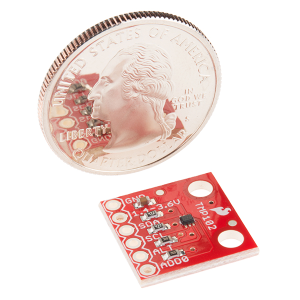
For the sensor itself, I went with Sparkfun's TMP102.  This little sensor is far more accurate than I need, but at 5$ a pop the whole thing, it was a great way to go.


SparkFun Digital Temperature Sensor Breakout - TMP102 


And finally, (while not originally planned), I also added a Noctua NF-A4x10 5V PWM to ensure that the sensor always was reading fresh air and not being unduly influenced by the heat generated by the rest of the box.


That all covers the main components of the devices themselves, but there will be other parts we'll get into further on.

How to collect the data?

Around the same time that I started thinking about how to build this project, I happened to also be jumping into the world of Home Automation.  While that whole project could be another post or series there-in, one of the things that I went with was using Home Assistant as the core OS.  As I played with it more I came to the realization:  "Wait, I need some software that's designed to collect data from a many sensors, store it, report on it, etc.  Home Assistant does this, and can run on something like a plain old Raspberry Pi too."  

 I happened to have a spare Pi 4 sitting around and an hour later I had it setup and running.  An hour after that I had figured out that the MQTT protocol (Message Queuing Telemetry Transport) would do what I needed and was compatible with some of the micro-controllers I had been looking at.  It was designed to be ultra lightweight and dead simple.

The Prototype Stage

With a rough idea now of what parts to use, what software to use, I set about getting a prototype done to prove it all out.  I ordered a couple of Picos, a couple of sensors, and 1 of the poe splitters.

It wasn't terribly difficult to get things going.  A few handy guides out there about hooking up an I2C sensor and I was off. 


Once I confirmed that yes, I can read the sensor value and it seems right.  I also got the network interface working and iterated on getting it to send messages to the Home Assistant that was running on the Raspberry pi.


While this is the early version of the display, future versions would clean this up a bit and make the color and theming better.


So you have some shiny electronics, what do you put them in?

During this time I'd also been conversing with one of my best friends about the project.  I was pretty sure no premade case was going to suffice.  If it was just the Pico, maybe, but I had gutted the PoE Splitter so that I had just the board, plus the temp sensor.  He has a 3D printer and had done quite a bit in that realm, so we went back and forth with some basic ideas.  This is where I did a weekend deep dive into the realm of designing parts for 3D printing.  I downloaded the free version of Fusion 360 and jumped in head first.

As I mentioned before, early versions of the case did not feature a fan.  At the time I didn't really think about needing one.  While the first "finished" version of the design and the final version have alot of similarities, I'll try to point out the big things along the way. And although I did the bulk of the work on these designs, I have to give a huge amount of credit to my friend.  He made several adjustments as we went and gave feedback on areas that he knew would likely be a problem due to my complete lack of 3D printing experience. 


The basic design was that there would be 3 chambers.  One chamber would house the pico, and the poe splitter, one chamber would hold the sensor and the final chamber would act as a buffer (and also be where a 4-20 1/4" threaded receiver would live for mounting).  It also would have a lip around to help the lid stay stable with the single screw in the middle. (at least in one of the versions anyway)


After getting the first drawing done though, it was suggested by my wife and friend both that heat could be a problem.  After sitting on that overnight, I decided to see what I could do about that.  A fan was the obvious answer, but given that this entire device is currently 100mm x 100mm x 20mm, there wasn't a ton of room.  At least not if I wanted to keep it in roughly the same size.  This is where I ended up deciding on the Noctua 40mm x 40mm x 10mm fans.  They are small, quiet, and really didn't require much in the way of a change in size.  As a bonus, these fans were PWM capable, so I could exercise control over how fast they ran.

Reworking the inside meant that we went from a 3 chamber design to a 2 chamber one.  The idea here was that the fan would sit in the main chamber, and pull air across the sensor from that chamber and dump it into the main one.  (see below on how the fan would fit).  The location of the mounting hole had to move here too; as did the hold for the wires to pass through for the sensor. 


With that, my friend felt like we had made it to the point where we could do a first print to get a feel for things.  Given that this was my first ever designed part for a 3D printer, I was pretty confident it was going to not go well, but honestly, it went alot better than I thought it would.


There were definitely problems in quite a few places.  The lip around the edge caused issues.  The single screw in the middle was going to cause flexing which would make the lid not sit quite right. (though we didn't know that yet)  The pegs for the Pico on  (on the left side of the image) weren't really going to hold it well enough and I messed up and didn't remove a piece of a wall which meant the pico couldn't even sit properly in it (see where the fan is).

There were probably other issues too, but those were the biggies.  For the V2 print, we fixed alot of those issues.  No more lip for most of it, and the pegs for the pico were replaced with holes for M2 heat set threaded inserts.  Also switched one of the pegs for the temp sensor to also be a heat set insert.  A hook was added to the end of the space for the pico to hold the back down and the base that the pico sat on was substantially reduced as it was pretty unnecessary now that it was screwed down.


We went through some more iterations, several of which involved just printing small parts of the structure to test various parts since printing the entire base takes about 5 hours to do.  Finally we neared what could be deemed as the first real test.  So he packed it up and shipped it to me (since I live several hours away).


With that I wired it up for the first real test.... would the dozens of hours spent so far actually work?


Well, yes, and no.  Did it turn on? Yup.  Did it report data? Yup.  Did the fan work?  Well, it spun and moved air, but work? No, no it did not. 

So what went wrong? Well, the space between the bottom of the fan and the bottom of the enclosure was just too small; only a few millimeters.  At anything above like 10% power, the air was just getting bounced back off the bottom and actually moving some air out of the main chamber and into the sensor chamber.  This was exactly the opposite of what it was supposed to do. 


So...now what?

Clearly this design wasn't going to work and I'll be honest, I went to bed rather frustrated that evening.  At this point this project is now already a month in and I had put in probably 30+ hours into it and it wasn't working like I wanted.  But with a new day meant a fresh mind to tackle it and so now to solve it. 

While completely redesigning the case was an option, it wasn't one I was in love with because there were alot of parts of the case that were in really good shape.  The tolerances were dialed in and things just fit.  So the goal was to try keep all the parts that were in good shape.

 Moving the fan seemed like the best bet, it would necessitate widening the box a little bit, but not a ton.  Doing it this way meant I could stick the fan right over the sensor and have it pull air directly from the above vent and push it out the bottom vent holes.  I also moved the mounting hole back onto this side to give myself a little more room in the main chamber to make the wiring less tight. And finally the pass-through hole was enlarged a bit since it'd need to accommodate 7 wires. (4 for the sensor, and 3 for the fan).


 My friend also put a logo and space for a label into the lid.


Another test print was done, which required 1 more iteration/adjustments that were mostly to fix either small tolerance errors, small measurement errors, etc.  In parallel my friend also considered how these should be transported.  He had printed a case from thingaverse for himself a while back and thought it could be modified to work.  After some iterative designing, he printed what would be the longest single print he's done on his printer.  Clocking in at just under 42 hours for the bottom part of the box, then another 12 hours for the lid, though it turned out great.


Assembly!

A full 2.5 months after starting this project and dozens of hours of effort it was finally time to assemble the full set of devices.  There were definitely setbacks.  In one stroke of immense skill, I managed to accidentally short 5v to ground on one of the Picos and successfully let the blue smoke out.  And once you let out the magic blue smoke, you can't put it back in.


I had to iterate a couple times but landed on this as the final layout of the wires. 


I bent some dupont connectors so that they would fit within the case height and that let me make it so I could plug everything either into the board directly or into a harness I made that comes off the PoE connector.  One thing to note is that I used the recommended way to supply external power to the board which is to feed it 5V through a schottky diode into VSYS.  This allows you to have both PoE and USB connected at the same time.  Though I found that for reliability, I need to plug in USB first then PoE, otherwise weird stuff happens.

I found while testing that 1 of the 6 Picos I had didn't want to ever boot when powered externally and only sometimes would boot when powered off of USB.  So I'm waiting for a replacement, but the other 5 have been working for a couple days now.  I mounted them all on a small piece of wood just to make it easier to have them up and working and the air flowing.


Done... Mostly

I still have to wait for the replacement Pico, but thankfully it'll just be soldering on the dupont connectors and flashing the firmware which all should take no more than 30 minutes.  I updated the Home Assistant with better visuals in the intervening months.  Also added the ability to control the speed of the fans via a simple button press.


And also got a PoE hat for the Raspberry Pi 4 and put on a spare one of those Noctua fans on it's little aluminum enclosure.  (also setup PWM on it too so it's not always flying at 100% when it doesn't need to).


Will it all do what I envision?

I don't know if this whole project will actually result in what I want.  I hope it does.  We'll see how well it actually works in the real world early next year.


The cost per device ultimately ended up being a bit more than I had originally envisioned.  Where I planned on them being closer to like $25-$30, they ended up being closer to $40 a piece due to the PoE and Fan addition. Even if it doesn't though, it was a fantastic learning experience and has driven me towards hopefully picking up a 3D printer of my own next year.

Once again I wanted to give a shout out to one of my two best friends.  He put in many hours to help with this when all I originally asked for was for him to print some stuff.  All told it was well over 100 hours of printing.  Also a shout out to my wife who would poke holes in some of my ideas. 


Friday, July 22, 2016

Custom Stairway + Hallway Lighting Project - Part 7 - Done. For Now.

The last 6 weeks have been rough on my time and health and stuff has taken far longer to get done, however, I've finally finished the project (or at least as finished as it can be for now).

A fair amount of fine tuning of the programming has occurred.  I found that the dimming was taking far longer than it should, so long that you could see each step down of the PWM signal.  I finally tracked this down to the debug logging I had in place.  It turns out that writing to the serial port is extremely expensive.  It could take upwards of 3-4ms to write out a line to the serial port.  Multiplying that out, some of the code was taking 40 or 50 ms per loop. (compared to my expectation of it taking a total of < 5ms to do all the checking and calculations and taking actions).  Once I removed the debug code, the fading out was much better.

I also added code to make the lights dimmer based on the ambient light of the sensors at the time that the lights were tripped.  The darker it is in the room the dimmer the lights are.  I'm still not totally settled on the lowest level of light and where the trigger levels are, but it's much closer now than it was before.

The next physical step in my work was to cut the channels in the drywall and run the power.  This necessitated a bunch of crawling around in my attic.  I'm not a fan of attics normally and I'm less so this one.  All of the HVAC runs around the attic and it makes moving from point A to point B annoying.  I used my oscillating saw to do the drywall cuts and it went pretty well.


I put some holes in the back of the aluminum channels so that I could screw them into the studs.  I did this because, like all wooden homes, there are slight variances in the wall.  It isn't perfectly straight and this would bend the channel to match the wall.  I also had to add some bracing at both ends where there were no studs.  I took a couple of small pieces of plywood and slide them in through the hole from the channel and screw them into the drywall.  It was a fun feat to do so without hurting myself or the wall.  This was done down the hall, below is the picture of just 1 half of it.


Once I got the channels in, I installed the lighting and tested it out to make sure that was all wired up right.  Then I puttied all the holes and sanded them.


And finally it was painted.


Next up was the sensors.  These were of a slightly different construction than the ones for the stairs.  Largely because you could see them and because they used PIR (Passive Infrared) sensors instead of Active Infrared sensors.  After search around I settled on using Christmas ornament shells that you could get from the local craft store (my wife's idea).

I used a step drill bit to drill out the hole for the sensor.  The picture doesn't show it, but I also cut that tab off then painted it.


For reasons I can't begin to explain, I forgot to take a picture of the finished inside of the sensor once the pcb and photo resistor was installed, but I did take a picture of the outside.


It turned out pretty well I think.


Monday, October 26, 2015

Custom Stairway + Hallway Lighting Project - Part 6 (Milestone!)

My parents came into town this past weekend though only for a short time.  They had a wedding to go to in a city about 2 hours away.  They were here Saturday Night through this morning.  That said, Sunday my father and I made great progress on the cabling and I finally have finished results for the first segment of the house: the stairs.  That said, I'm really sore today.  Spent alot of time contorting myself around the furnace closet to pull and run wires.  Thankfully only minor scrapes and bruises were had.

Before they got here, I needed to get the rails up.  To get the rails up I needed to put ends on both the Cat5 and the power wires.  This was a mostly uneventful affair.  I am using XT60 polarized terminals for the power.  Normally these things are used for RC cars/planes battery connections, but their ratings make them ideal for this application as well.  The only hard part about this is getting 16 gauge wire and connectors to hold them hot enough to flow solder, but not so hot as to melt the wires and or the connectors is a pain.  But overall it looks pretty good.


I used a standard keystone jack for the networking.  Between this and the XT60, getting the rail off the wall is pretty easy.  I did offset the connectors by about 1" in length so that only 1 connector would need to come out of the hole in the wall at a time.


The first order of business when my father and I started was to cut a hole in the wall of the HVAC room.  The nice thing is that this room is unfinished (seriously even the mudding is terrible, they didn't bother to sand or anything).  I used my Black and Decker oscillating saw to do the cuts.  That has to be one of my favorite tools.  It cuts drywall like butter and for the most part is clean cuts if you are careful. I forgot to take a picture after we took this out, but it was an empty space with studs, so you probably can imagine that (or maybe not).


Initially the plan was to use my 12" long 5/16" bit to drill down, but we figured out that with the studs and the floor joists that was just too short.  We ended up getting a 9/16" 36" boring bit.  A little costly, but it worked like a charm.  We got the wires fished and ends put on them. The hole in the wall is just a little bigger than the keystone, but small enough that the end of the rail hides it entirely.


I needed power in the closet so we pulled it in from an outlet on the other side of the wall.  Of course that was on the other side of the wall from where everything else was.  We used wire molding to get it over to the other side.  There is a drain near where the outlet ended up (about 3' below it), so we ended up using a GFCI outlet, just in case.  Normally this stuff is stick on, but we used some screws into the studs to re-enforce it.  The space on the left of the room is only about 12" wide.  Lots of contorting around to get back there.


We also ran some molding to carry the cat 5 and power wires from the wall over to the box.


And then we hung the box.  2 screws into a stud and 2 into metal drywall anchors.  I do plan to put some Velcro wraps around the cables to clean them up some.  I also need to print out cable labels too.


And finally. Let there be light....


We finished late and initially the bottom stairs sensors weren't functioning.  Quick diagnosis showed that the values were all over the place as if the pins were floating (not connected).  But girl child was needing to go to bed, so it waited until this morning.  I found that the connector at the end of the cable in the closet had 2 of the wires switched.  (specifically +5V and the input for the resistor.  Thankfully that specific configuration couldn't have hurt anything, but it would make everything crazy unstable.

So what's next?  Well there is some fine tune programming that needs to happen.  I need to adjust the light sensor levels so that the lights don't turn on during the day and also program the logic to adjust the max light level based on the initial light levels. (so the brigher it is in the room, the the brighter the lights are.  When it's really dark and your eyes are used to it being dark full power is too bright.

Once that is done then it will be time to plan out the details for the other 2 hallways.  I have the general plans of course, but I need to figure out exact measurements so I can buy the lights and channels.  I also still need to pick up a couple more photo resistors and PIR sensors.

Friday, October 23, 2015

Custom Stairway + Hallway Lighting Project - Part 5

It has taken me almost 2 weeks to get through the next steps of the project.  I spent an hour or 2 most afternoons/evenings working on the smaller of the 2 hand rails.  A lot of that time was just spent figuring out how to approach it.

There were several problems to solve.  First, how to route the path into the wood to hold the aluminum channel.  Second, how to get the wires through wood.  the power wires only needed to be at one end, but due to how my walls are laid out I needed to run the sensor wires the entire length of the wood.

I started with drilling the access holes to bring power into the rail.  These holes were drilled with a 5/16" bit and a hand drill.  Overall I ended up coming very close to my target.  On the right I added some red lines to give you a general idea of where the holes were drilled.  Keep in mind I had to drill off center so that I'd miss the area where the holes were drilled for the brackets. 


My approach for this rail was to use a 1/4" routing bit on the routing table.  I drew up lines on where I wanted the cuts to go.  For some reason I didn't take a picture directly after this step, but here is what it looked like right before.


Here you can see part of the routing job and also the connecting hole.  Overall I was not pleased with the routing job.  There were quite a few problems with it.  The first of which was that the bit I had really wasn't designed for hogging out that much wood.  The second was that it was very difficult to measure exactly where to set the backplane when you can't see the thing you're routing out.  It was also difficult to control and that caused bumps.   That said it did work and all the less desirable look of it will be hidden under the aluminum channel.  You'll also note that in the center of the channel it is deeper than on the edges.  This is the place where the I/O lines will run.


So even though it didn't look great underneath it looked pretty good with the channel in.  This was a dry fit of course, there was a lot of work left to do.


I needed to figure out exactly what shape the sensor box was going to be. Below are all of the pieces (except a small capacitor) that needs to be dealt with.  The PCB actually goes into the black box there.  I knew I was going to use acrylic to make a box that I could paint and thus mostly hide.


Like the other side, I needed to drill holes into the sides of the rails to provide access to fish the lines through.  Additionally another hole needed to be drilled where the sensor box was going to go.


Here you can see the 2 horizontal holes and 1 vertical hole.  The very long horizontal hole was drilled with a 12" 5/16" bit.  I took a small 2x4 and put a 5/16" hole into it at the height I wanted using the drill press so it was exactly square.  I then clamped the 2x4 to the end of the rail to provide a guide so that the bit wouldn't drift over such a long distance.


I decided a good place to put the photoresistor was in the empty space of the IR sensor.  So I drilled a couple holes in the plastic and stuck it in.  Then I filled it with some silicon to insulate it.  (Though I'm thinking hot glue next time.)


Next up was the wonderful fun of wire fishing.  The holes I drilled were just 1 size bigger than the bare minimum, so pulling this stuff around corners was a challenge.  Even more so for the network cable as it is solid core with riser rated insulation, which makes it stiff.  I ended up having to shed the outer insulation at both ends to make the turns.  Not a huge deal, it's surrounded by 3/4" of wood, so it's pretty safe.


On the other end I had to bring in both power and the I/O cable.  I ended up using 1 line of power (which was pretty easy to move through by itself) to first pull the other line of power which also had I/O cables taped to it.


After the wires went in I went to building the acrylic box to house the sensors.  I also painted the sensors once with white spray paint.  The boxe's outside was sanding down so that it would take the paint better since I want it to be the same color as the rail.


Next up was to start cleaning this rail up so that it looks like it did before.  Using some Bondo (which I've never used before, but holy crap it stinks), I filled the 3 holes that aren't going to be used going forward and which can be readily and easily seen.


While waiting for the Bondo to cure, it was time to start getting the led strips into the channel which includes cutting one of them to that it will fit


After sanding the Bondo down to match the wood, I put on the first coat of paint (which would be a total of 4 coats, 2 on bottom half, 2 on top half.  All this work so far has marked the heck out of the rails.


Finally putting in the aluminum channel for near the last time.  It fits quite well.  I ended up using some black electrical tape on the back, not to adhere it to the channel, but because the back of the strip has metal contact points that I very much don't want to short.


And Finally this one is now done! (well almost still need to put ends on the wires before they go into the walls, but I am not going to do that until I determine how much slack I want there.


So after my adventures with the short rail I learned a few things to make the 2nd one go *much* faster and mostly easier. Two big changes with this one vs the other one.  The first is how I went about routing out the holes.  I purchased a top-bearing 1/2" router bit with a 1/4" cut depth.  I then got 2 pieces of square steel tubing and used those as the guide for the bearing.  Most this approach worked.  The worst part was that I expected the steel tubing to be straight.  That was not the case though as it tended to bow some.  The cuts were cleaner, but not perfect.

The second change was to route out the entire channel all the way from the first bracket to the last.  The reason is I still needed to get the wire all the way down and I had 2 brackets in the middle to deal with.


Like the other one, I did 2 levels of routing for the wires.  In the picture below, though its hard to tell.  I took the bearing off of the bit and cut under the wood.  This gave me most of a channel to run the wires in.  It wasn't quite enough, but that's ok.  The wood insert I'll be cutting to replace the wood I routed out can handle it.


Next using the same approach as last time I fished the wires through both ends.


I needed to replace the wood that I routed.  To do that I cut out a piece of poplar and then used the band saw to cut notches into it.  I then glued it into place and after letting it set, sanded it down to be flush with the rail.  The band saw cuts weren't the greatest, but they were close enough.  Once the channels are in, no one will be the wiser.  (except everyone who reads this, all 5 of you).


Time precluded me taking pictures of putting the channels in and soldering stuff, but here is the finished product.


At the same time I was doing the rails I had a few more modifications I thought I should make to the controller.  The first was to add a fuse to the 12V rail.  Since I'm sticking wires in the wall, even low voltage ones, I'd rather be safe than sorry.  I got fast blow glass fuses and stuck a 6 Amp one in.  Another thing was that the override button showed up.  This was a 12V LED latching vandal switch.  When pressed it would suspend all the I/O and simply turn the lights on full.  

While testing that though I found something odd.  The LED in the switch was on, but dimly.  This was odd because the LED doesn't share a circuit with the switching mechanism itself and I was only powering the micro controller via USB.  The 12V supply wasn't plugged in.  I realized that when the microcontroller is plugged into USB, the regulated 5V supply actually comes out of the voltage input line.  This was bad because neither the micro-controller nor USB is capable of driving the current that the 12V rail was supposed to support.  To that end I added 2 diodes to the system.  One on Vin on the microcontroller and one right after Gnd on the micro controller.  This way the controller can't accidentally try and power the 12v bus.


And here is the new schematics.


I also found a bug in the calculations for the distance sensor.  I forgot when I switched it to the new averaging method that I was initializing the base total with values at 100 for each.  The problem is that was skewing the average to 30-35" instead of what it really was which was usually 15-20".  Also needed to add the code to handle the switch.

Next up is finally seeing some results.  I need to put the rails back up at least for the weekend since my parents are in town, but I'm hoping my father will be able to help run the wires in the wall up into the HVAC room.  Then just plug everything in and turn it on and hope it doesn't explode.  (pretty sure it won't after all the testing, but...)