It has taken me almost 2 weeks to get through the next steps of the project. I spent an hour or 2 most afternoons/evenings working on the smaller of the 2 hand rails. A lot of that time was just spent figuring out how to approach it.
There were several problems to solve. First, how to route the path into the wood to hold the aluminum channel. Second, how to get the wires through wood. the power wires only needed to be at one end, but due to how my walls are laid out I needed to run the sensor wires the entire length of the wood.
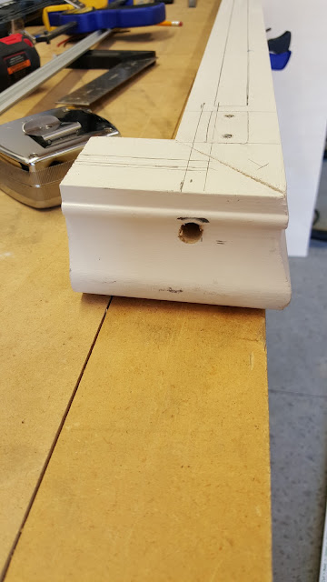
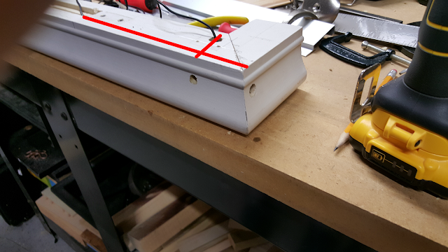
I started with drilling the access holes to bring power into the rail. These holes were drilled with a 5/16" bit and a hand drill. Overall I ended up coming very close to my target. On the right I added some red lines to give you a general idea of where the holes were drilled. Keep in mind I had to drill off center so that I'd miss the area where the holes were drilled for the brackets.
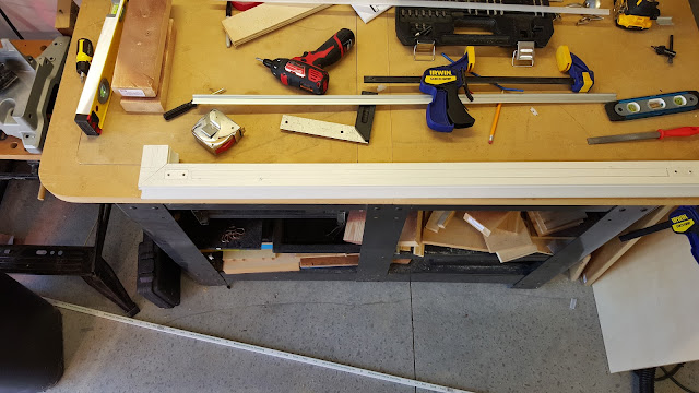
My approach for this rail was to use a 1/4" routing bit on the routing table. I drew up lines on where I wanted the cuts to go. For some reason I didn't take a picture directly after this step, but here is what it looked like right before.
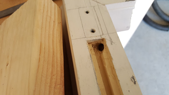
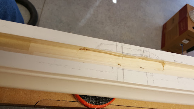
Here you can see part of the routing job and also the connecting hole. Overall I was not pleased with the routing job. There were quite a few problems with it. The first of which was that the bit I had really wasn't designed for hogging out that much wood. The second was that it was very difficult to measure exactly where to set the backplane when you can't see the thing you're routing out. It was also difficult to control and that caused bumps. That said it did work and all the less desirable look of it will be hidden under the aluminum channel. You'll also note that in the center of the channel it is deeper than on the edges. This is the place where the I/O lines will run.
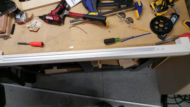
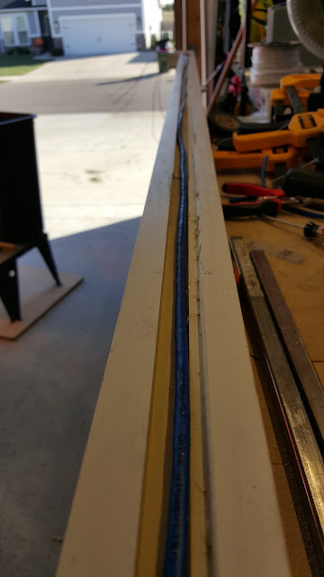
So even though it didn't look great underneath it looked pretty good with the channel in. This was a dry fit of course, there was a lot of work left to do.
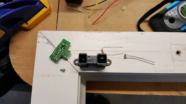
I needed to figure out exactly what shape the sensor box was going to be. Below are all of the pieces (except a small capacitor) that needs to be dealt with. The PCB actually goes into the black box there. I knew I was going to use acrylic to make a box that I could paint and thus mostly hide.
Like the other side, I needed to drill holes into the sides of the rails to provide access to fish the lines through. Additionally another hole needed to be drilled where the sensor box was going to go.
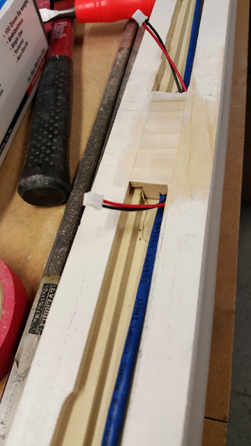
Here you can see the 2 horizontal holes and 1 vertical hole. The very long horizontal hole was drilled with a 12" 5/16" bit. I took a small 2x4 and put a 5/16" hole into it at the height I wanted using the drill press so it was exactly square. I then clamped the 2x4 to the end of the rail to provide a guide so that the bit wouldn't drift over such a long distance.
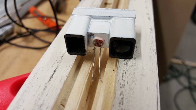
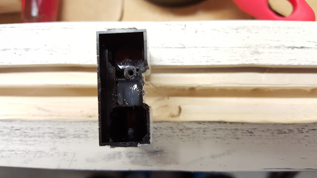
I decided a good place to put the photoresistor was in the empty space of the IR sensor. So I drilled a couple holes in the plastic and stuck it in. Then I filled it with some silicon to insulate it. (Though I'm thinking hot glue next time.)
Next up was the wonderful fun of wire fishing. The holes I drilled were just 1 size bigger than the bare minimum, so pulling this stuff around corners was a challenge. Even more so for the network cable as it is solid core with riser rated insulation, which makes it stiff. I ended up having to shed the outer insulation at both ends to make the turns. Not a huge deal, it's surrounded by 3/4" of wood, so it's pretty safe.
On the other end I had to bring in both power and the I/O cable. I ended up using 1 line of power (which was pretty easy to move through by itself) to first pull the other line of power which also had I/O cables taped to it.
After the wires went in I went to building the acrylic box to house the sensors. I also painted the sensors once with white spray paint. The boxe's outside was sanding down so that it would take the paint better since I want it to be the same color as the rail.
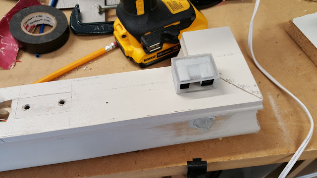
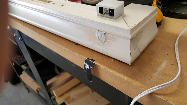
Next up was to start cleaning this rail up so that it looks like it did before. Using some Bondo (which I've never used before, but holy crap it stinks), I filled the 3 holes that aren't going to be used going forward and which can be readily and easily seen.
While waiting for the Bondo to cure, it was time to start getting the led strips into the channel which includes cutting one of them to that it will fit
After sanding the Bondo down to match the wood, I put on the first coat of paint (which would be a total of 4 coats, 2 on bottom half, 2 on top half. All this work so far has marked the heck out of the rails.
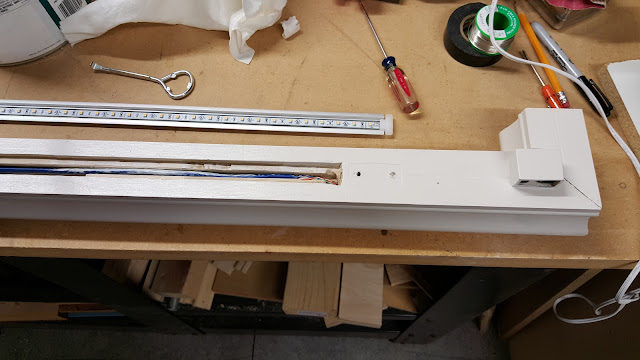
Finally putting in the aluminum channel for near the last time. It fits quite well. I ended up using some black electrical tape on the back, not to adhere it to the channel, but because the back of the strip has metal contact points that I very much don't want to short.
And Finally this one is now done! (well almost still need to put ends on the wires before they go into the walls, but I am not going to do that until I determine how much slack I want there.
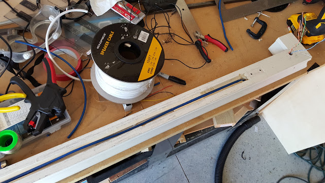
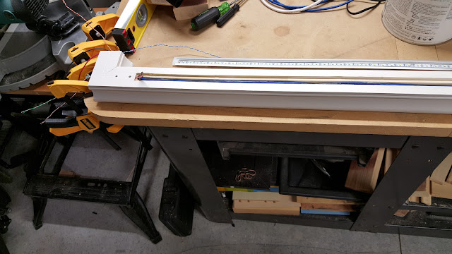
So after my adventures with the short rail I learned a few things to make the 2nd one go *much* faster and mostly easier. Two big changes with this one vs the other one. The first is how I went about routing out the holes. I purchased a top-bearing 1/2" router bit with a 1/4" cut depth. I then got 2 pieces of square steel tubing and used those as the guide for the bearing. Most this approach worked. The worst part was that I expected the steel tubing to be straight. That was not the case though as it tended to bow some. The cuts were cleaner, but not perfect.
The second change was to route out the entire channel all the way from the first bracket to the last. The reason is I still needed to get the wire all the way down and I had 2 brackets in the middle to deal with.
Like the other one, I did 2 levels of routing for the wires. In the picture below, though its hard to tell. I took the bearing off of the bit and cut under the wood. This gave me most of a channel to run the wires in. It wasn't quite enough, but that's ok. The wood insert I'll be cutting to replace the wood I routed out can handle it.
Next using the same approach as last time I fished the wires through both ends.
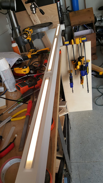
I needed to replace the wood that I routed. To do that I cut out a piece of poplar and then used the band saw to cut notches into it. I then glued it into place and after letting it set, sanded it down to be flush with the rail. The band saw cuts weren't the greatest, but they were close enough. Once the channels are in, no one will be the wiser. (except everyone who reads this, all 5 of you).
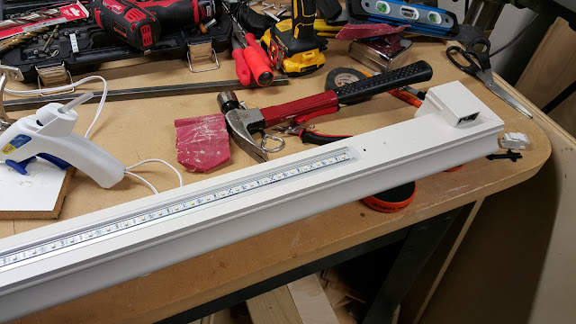
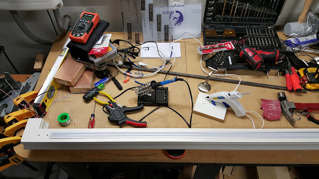
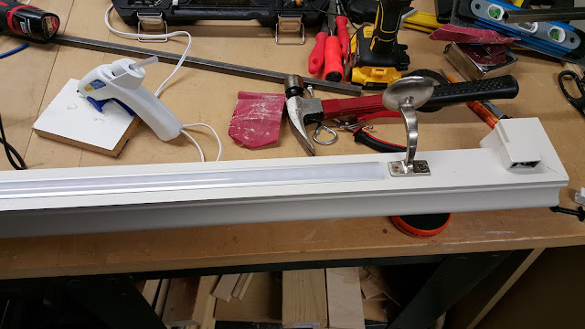
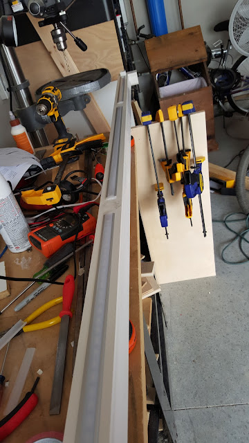
Time precluded me taking pictures of putting the channels in and soldering stuff, but here is the finished product.
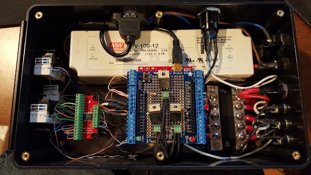
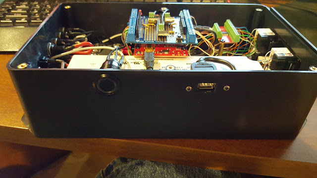
At the same time I was doing the rails I had a few more modifications I thought I should make to the controller. The first was to add a fuse to the 12V rail. Since I'm sticking wires in the wall, even low voltage ones, I'd rather be safe than sorry. I got fast blow glass fuses and stuck a 6 Amp one in. Another thing was that the override button showed up. This was a 12V LED latching vandal switch. When pressed it would suspend all the I/O and simply turn the lights on full.
While testing that though I found something odd. The LED in the switch was on, but dimly. This was odd because the LED doesn't share a circuit with the switching mechanism itself and I was only powering the micro controller via USB. The 12V supply wasn't plugged in. I realized that when the microcontroller is plugged into USB, the regulated 5V supply actually comes out of the voltage input line. This was bad because neither the micro-controller nor USB is capable of driving the current that the 12V rail was supposed to support. To that end I added 2 diodes to the system. One on Vin on the microcontroller and one right after Gnd on the micro controller. This way the controller can't accidentally try and power the 12v bus.
And here is the new schematics.
I also found a bug in the calculations for the distance sensor. I forgot when I switched it to the new averaging method that I was initializing the base total with values at 100 for each. The problem is that was skewing the average to 30-35" instead of what it really was which was usually 15-20". Also needed to add the code to handle the switch.
Next up is finally seeing some results. I need to put the rails back up at least for the weekend since my parents are in town, but I'm hoping my father will be able to help run the wires in the wall up into the HVAC room. Then just plug everything in and turn it on and hope it doesn't explode. (pretty sure it won't after all the testing, but...)












No comments:
Post a Comment